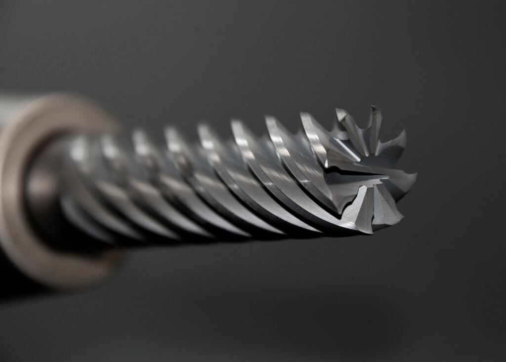
Design for manufacturing.

The rules our engineers use to review 400+ parts a week. Design to these numbers and your parts get cheaper, faster and more reliable, wherever you build them.

Guide 01 · 8 min read

CNC machining design rules

Most CNC cost comes from three things: how many setups a part needs, how long the tool is in the cut, and how many special tools are required. These rules keep all three low.
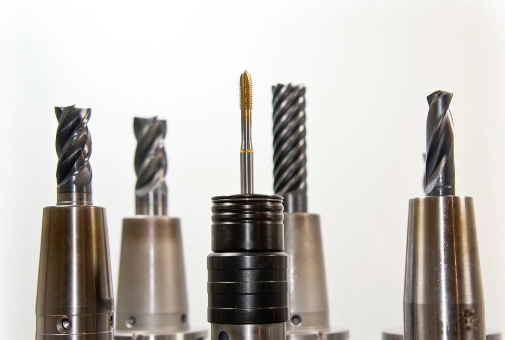
Solid carbide end mills of different sizes
FeatureRecommendedWhy it matters
Internal corner radius≥ 1/3 of cavity depthEnd mills are round. A slightly larger radius than the tool lets it keep moving instead of stopping in the corner, which improves finish and tool life.
Cavity depth≤ 4× cavity widthLong, thin tools deflect and chatter. Deep pockets need slower cuts or special tooling.
Wall thickness≥ 0.8 mm metal · ≥ 1.5 mm plasticThin walls vibrate during cutting and may warp once released from the fixture.
Hole depth≤ 4× diameter (standard)Up to 10× is possible with peck drilling, but costs more. Use standard drill sizes where you can.
Thread length≤ 3× diameterAlmost all thread strength is in the first 3 turns. Deeper threads add cycle time without adding strength.
Text & engravingEngraved, ≥ 20 pt sans-serifEngraved text is cut with one small tool. Embossed (raised) text removes far more material.
UndercutsStandard widths: 3–40 mmUndercuts need T-slot or dovetail cutters. Stick to standard sizes so we don't grind a custom tool.
SetupsDesign for 1–2 orientationsEvery re-fixture adds cost and a chance of misalignment. Group features on as few faces as possible.
Engineer's tipAdd a 0.5 mm chamfer instead of a fillet on external edges. A chamfer tool cuts every edge in one pass; external fillets need a ball mill and far more toolpath.
Guide 02 · 6 min read

Sheet metal fundamentals

Sheet metal parts are cut flat and then bent. Most problems come from features too close to a bend, where the metal stretches and distorts. Design from the material thickness (T) outward.

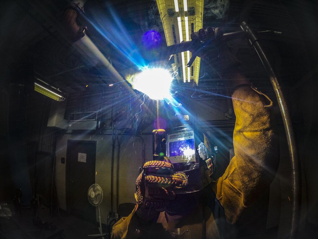
Sheet metal frame being welded
FeatureRecommendedWhy it matters
Inside bend radius≥ 1× TTighter radii crack harder alloys like 6061-T6. Use one radius across the part so a single tool forms every bend.
Minimum flange length≥ 4× TThe flange must rest across the press-brake die opening to bend cleanly.
Hole to edge distance≥ 2× THoles too near an edge bulge or tear during cutting and forming.
Hole to bend distance≥ 2.5× T + bend radiusCloser holes stretch into ovals as the metal bends.
Minimum hole diameter≥ 1× TSmaller holes are possible on the laser but leave rough edges and heat marks.
Bend reliefWidth ≥ T, depth ≥ radius + TRelief cuts stop tearing where a bend meets an unbent edge.
Bend tolerance±0.5° standardTighter angles are achievable with angle-measuring brakes but add inspection time.
Engineer's tipUse a hardware specification (PEM nuts, studs and standoffs) instead of tapped threads in sheet under 3 mm thick. They're stronger and cost less to install than tapping thin material.

Guide 03 · 7 min read

Injection molding essentials

A mold is a large up-front investment, so design changes after tooling are expensive. Getting walls, draft and ribs right before the tool is cut is the single biggest lever on part quality.

FeatureRecommendedWhy it matters
Wall thickness1.2–3 mm, uniformUneven walls cool at different rates, causing sink marks, voids and warp.
Draft angle≥ 1° (≥ 3° on textured faces)Draft lets the part release from the mold without drag marks or ejector damage.
Rib thickness50–60% of wallThicker ribs leave visible sink marks on the opposite (cosmetic) side.
Rib height≤ 3× wall thicknessTall ribs are hard to fill and to eject.
Boss outer diameter2× screw diameterConnect bosses to walls with ribs instead of thickening them.
Corner radiusInside ≥ 0.5× wallSharp corners concentrate stress and restrict material flow.
UndercutsAvoid, or plan side actionsEach side action or lifter adds tool cost and maintenance.
Engineer's tipAsk for a mold-flow analysis before steel is cut. We include one free with every production tool. It shows weld lines, air traps and warp before they cost you a tool modification.

Guide 04 · 5 min read

Designing for additive

Additive frees you from tool access, but it introduces its own rules around overhangs, supports and powder removal.

FeatureMetal (DMLS)Polymer (SLS / MJF)
Minimum wall0.4 mm0.8 mm
Self-supporting overhang≥ 45° from horizontalNo supports needed
Minimum hole0.5 mm1.5 mm
Escape holes (hollow parts)≥ 2 × Ø3 mm≥ 2 × Ø5 mm
Typical tolerance±0.1 mm + 0.1%±0.3 mm + 0.3%
Post-machiningLeave 0.5 mm stock on critical facesRarely needed

Guide 05 · 5 min read

How tight is too tight?

Over-tolerancing is the most common cost driver we see. Every extra decimal place means slower cutting, more inspection and sometimes a different machine. Tighten only the features that need it, and let a general tolerance block cover the rest.

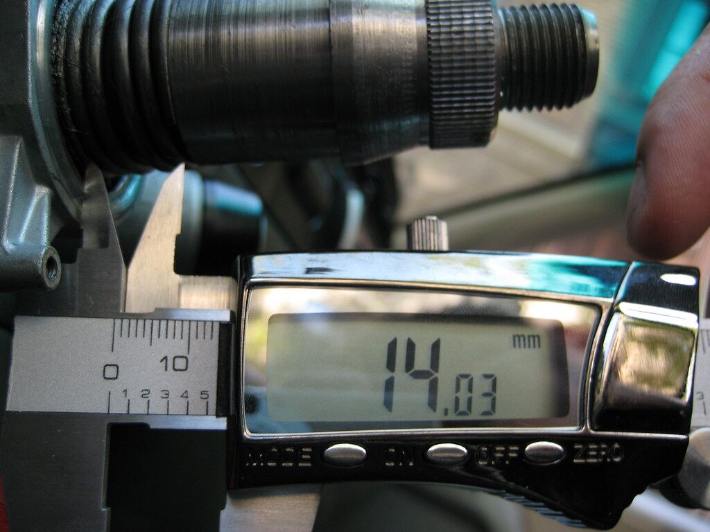
Digital caliper reading 14.03 mm
ToleranceTypical useRelative cost
±0.25 mmNon-critical external features, clearance holes1.0×
±0.10 mmOur standard. Most mating features1.0×
±0.05 mmLocating features, press-fit bores1.2–1.5×
±0.025 mmBearing seats, precision alignment1.5–2.5×
±0.005 mmOptical, metrology, valve spools. Often needs grinding3–5×
Engineer's tipUse GD&T position tolerances for hole patterns instead of tight ± dimensions on each hole. A ±0.05 mm square zone rejects good parts at its corners; a Ø0.14 mm position zone accepts the same worst-case corners and gives 57% more usable area, at no loss of function.

Guide 06 · 4 min read

Choosing a surface finish

Finishes protect parts and set how they look and feel. Remember that coatings add thickness, so critical dimensions may need masking or adjusted machining.

FinishMaterialsThickness addedBest for
As machinedAll0Prototypes, internal parts. Ra 3.2 µm typical
Bead blastAll metals0Uniform matte look, hides tool marks
Anodize Type IIAluminum5–25 µmColor, corrosion protection, consumer products
Anodize Type IIIAluminum25–75 µmWear resistance, aerospace and defense
PassivationStainless steel0Medical and food contact, corrosion resistance
Powder coatSteel, aluminum50–150 µmDurable color on enclosures and frames
Electroless nickelSteel, aluminum, copper5–25 µmUniform hard coating, even in bores

Reference

Manufacturing glossary

DFM
Design for Manufacturing. Reviewing a design to make it easier and cheaper to produce without changing its function.
FAI (AS9102)
First Article Inspection. A full measurement of the first production part against every drawing requirement.
CMM
Coordinate Measuring Machine. A precision probe that measures part geometry in 3D, often to within a few microns.
PPAP
Production Part Approval Process. The automotive standard for proving a process can consistently make good parts.
CoC
Certificate of Conformance. A signed statement that parts meet the order and drawing requirements.
Cpk
Process capability index. Shows how well a process stays within tolerance. 1.33 or higher is generally considered capable.
GD&T
Geometric Dimensioning and Tolerancing. A symbolic language for defining form, orientation and position on drawings.
Ra
Average surface roughness, in micrometers. Lower is smoother. Ra 0.8 µm feels smooth; Ra 0.1 µm looks like a mirror.
T1 sample
The first parts shot from a new injection mold, used to verify the tool before production.
Lights-out machining
Automated machining that runs unattended overnight, lowering cost and lead time.

Your next part is 24 hours from a real quote.

Join 1,200+ engineering teams who build with Torvane.

Call Get a quote in 24h